The other day my torche (pole) lamp failed to turn on. It’s one of those with a three setting rotary switch (off, low, high) and a halogen bulb. So we set about debugging/fixing it.
We tried the following :
- Acquire new bulbs
- Test old bulb
- Test switch
- Bypass switch
- Properly test switch
- Do the math
- Compare new and old bulb
Acquire new bulbs
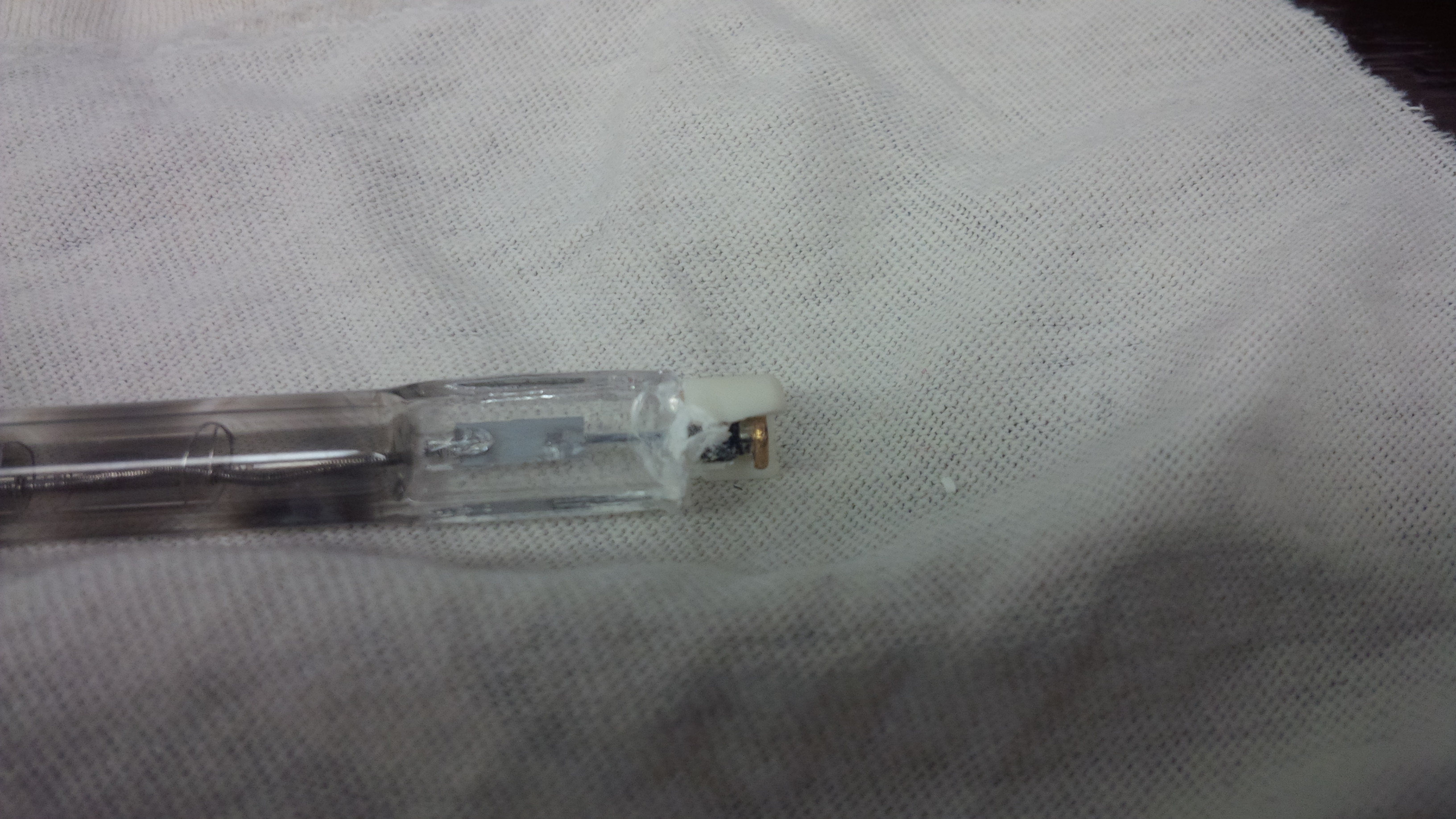
Our first stop was to the hardware store to buy some replacement bulbs. The first snag was that the lamp and old bulb had no markings indicating what wattage it was. When the bulbs are new they have markings on the end which say what voltage and wattage they are. Apparently this is the first thing to burn off. The trick is to use the old filament size as a reference when looking for a new one. In our case 150W was too small and 300W and 500W were too thick. This left the 200W bulbs and they looked about right.
Test old bulb
Upon visual inspection the old bulb looked fine other then the ceramic at both ends which was actively crumbling away. So we tested it with a multimeter in conductivity mode (the one that goes beep beep when there is a low resistance path detected). No dice but this wasn’t surprising. If it failed open there would be no circuit. If it was still functional it would have a high resistance and not trigger the beep beep. Next we measured the resistance and found it to be aproximately 620$k \small{\Omega}$. We assumed this meant the bulb was still functional therefore it was likely the switch that was bad.
Test Switch
To test the switch without a bulb in the socket we used our 120V sensor. It goes beep and lights up if it senses 120V nearby. Usefull to make sure the power is actually off before working on 120V switches or outlets. We plugged in the lamp and sure enough our sensor beeped near the outlet. We moved it up to the socket and cycled through the switch positions. No joy but it did twitch when we moved it away from the socket. So we assumed it was the switch and moved on to bypassing it.
Bypass Switch
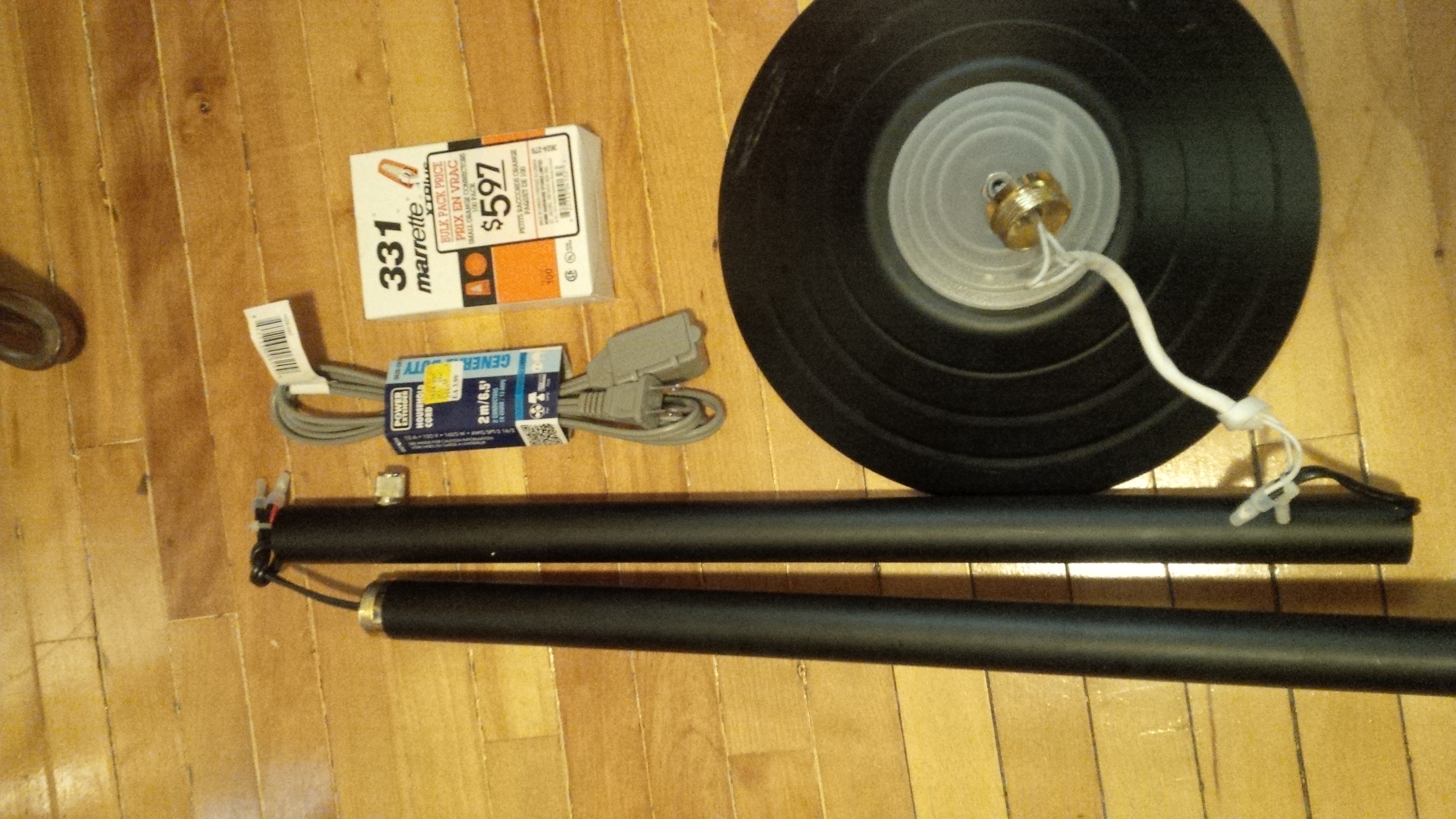
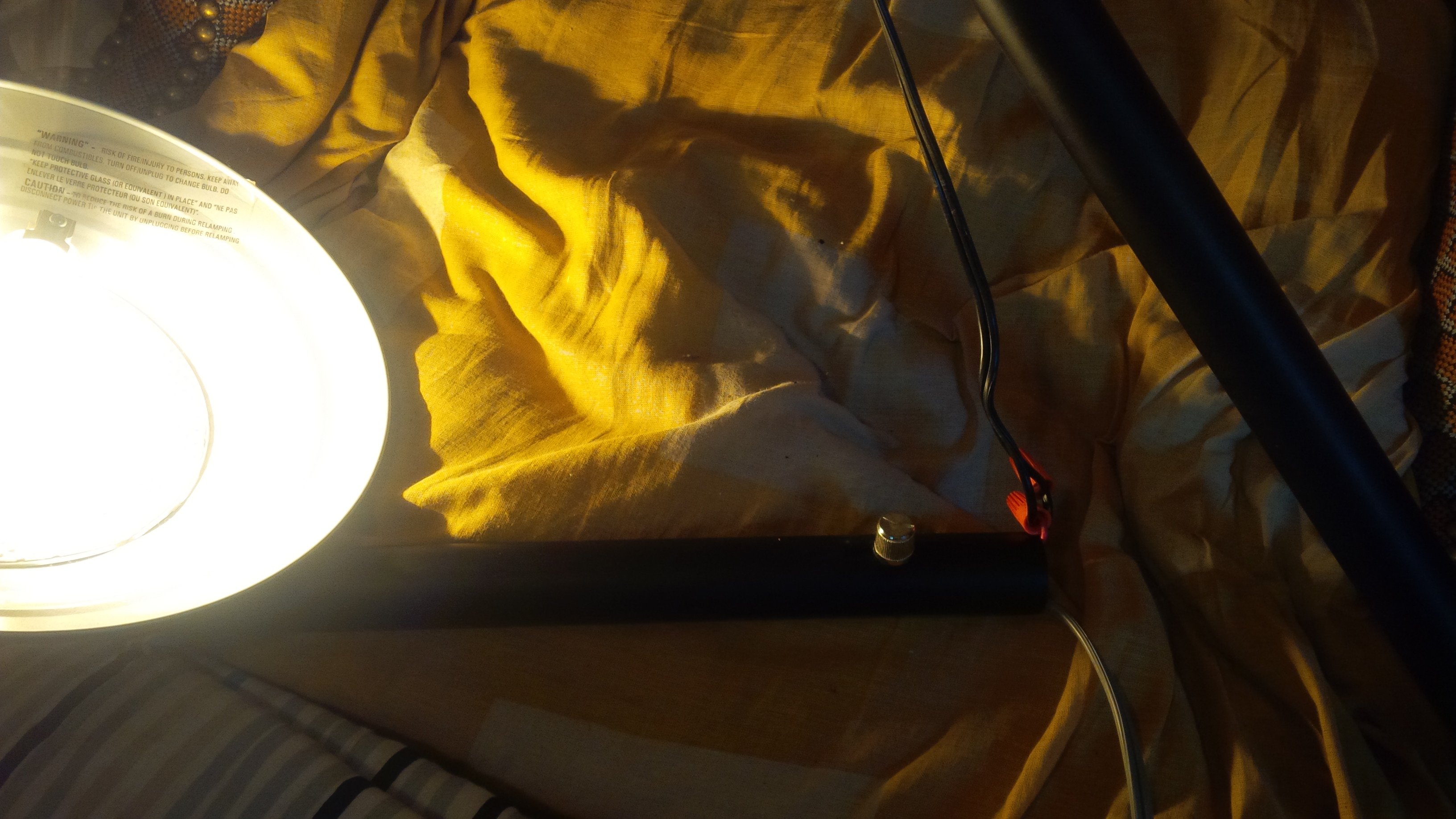
We bought a 2ft two prong extension cord and some marrets from the hardware store. Per foot it was about the same price as wire on its own plus it came with plugs. Opening the lamp we found the switch was independent of the wire running from the wall and after to the bulb. So we disconnected the switch and ran a chunk of the sacrificed extension cord pass it connecting it to the relavent wires with marrets and some electrical tape. Reassembling and applying power and voila, let there be light. Success.
Properly Test the Switch
I wasn’t convinced that the switch was the problem so I used a multimeter to test conductivity of the switch by twisting the far end of the wires together and probing the near end. One of the switch positions had conductivity meaning it might not be broken. So we wired the switch back into the circuit and applied power. And voila, there was light. Obviously we only needed to replace the bulb so what did we miss?
Do the math
Our father has a saying “When in doubt, do that math”. So for a 200W bulb we would expect the resistance to be roughly $50 \small{\Omega}$ since $V=IR$ and $W=VI=\frac{V^2}{R}$ so $R=\frac{V^2}{W}$. So 620$k \small{\Omega}$ is rather high. This is of course assuming a halogen bulb behaves like an incandesent bulb in terms of resistance.
Compare Old and New bulbs
When we tested the resistance of a new bulb we got $6 \small{\Omega}$ and when we retested the old bulb we got $12 M\small{\Omega}$. $6\small{\Omega}$ is much smaller then the expected $50 \small{\Omega}$ but that’s because of the difference in cold vs operating resistance. As the bulb heats up the resistance goes up. Also when I was testing the switch with the new bulb my sensor beeped going up the outside of the pole. It didn’t do that when I first tested the switch meaning I likely didn’t have the sensitivity set correctly.
Putting it all back together
So now we have to put everything back together with the switch back in use. But which wire goes were? Since it’s AC current it doesn’t matter, right? For something basic without a switch, yes, which wire is which doesn’t matter. But for things with a switch the live should go to the switch. This is because we want to make sure if the switch is off the bulb sockets are off. In the other orientation the switch is can be off but the bulb sockets are still live whenever the plug is connected to the wall. You should never work on a live system but live going to the switch gives one extra layer of protection.
OK so which pin on a polarized plug is the live? According to 2-Prong Electric Plug Wiring it’s the smaller of the two. So we used our good old multimeter to figure out which wire went to the smaller pin and connected that to the red wire of the switch. No gaurentee that that was the one going to the switch but it’s a reasonable guess since in DC wiring red = power, black = ground, any other color = signal. We could also have just used the multimeter and found the wire that bypassed the switch. To verify we used our 120V sensor and sure enough when the switch was on there was power at the bulb socket and when off no power at the bulb socket.
What we should have tried
- Acquire new bulbs
- Try new bulb
- Compare new and old bulb if necessary
- Test switch if necessary
- Bypass switch if necessary
If we’d done this we would have just swapped out the bulb and saved ourselves over an hour of work not including hardware store runs.
Things we (re)learned
- Use the filament size to choose the new bulbs
- Always compare against a known good reference
- Debug from simple to complex
- Debugging thoroughness makes a difference
- When in doubt do the math.
References
- 2-Prong Electric Plug Wiring (Chris Deziel)
- Say Goodbye to the Incandescent Lightbulb (Chuck Newcombe)